Magnetic Effects of Electric Current
We know that an electric current-carrying wire behaves like a magnet. Let us perform the following Activity to reinforce it.
The compass needle is deflected on passing an electric current through a metallic conductor

We see that the needle is deflected. What does it mean? It means that the electric current through the copper wire has produced a magnetic effect. Thus we can say that electricity and magnetism are linked to each other.
In this chapter, we will study magnetic fields. We shall also study electromagnets and electric motors which involve the magnetic effect of electric current, and electric generators which involve the electric effect of moving magnets.
Hans Christian Oersted (1777–1851)

Hans Christian Oersted, one of the leading scientists of the 19th century, played a crucial role in understanding electromagnetism. In 1820 he accidentally discovered that a compass needle got deflected when an electric current passed through a metallic wire placed nearby. Through this observation, Oersted showed that electricity and magnetism were related phenomena. His research later created technologies such as the radio, television and fiber optics. The unit of magnetic field strength is named the oersted in his honour.
Compass
A compass needle is, in fact, a small bar magnet. The ends of the compass needle point approximately towards north and south directions. The end pointing towards the north is called north seeking or north pole. The other end that points towards the south is called south seeking or south pole.
Magnetic Field and Field Lines
Iron filings near the bar magnet align themselves along the field lines.

The iron filings arrange themselves in a pattern as shown in Fig. Why do the iron filings arrange in such a pattern? What does this pattern demonstrate? The magnet exerts its influence in the region surrounding it. Therefore the iron filings experience a force. The force thus exerted makes iron filings arranged in a pattern.
Magnetic Field
The region surrounding a magnet, in which the force of the magnet can be detected, is said to have a magnetic field.
Magnetic field is a quantity that has both direction and magnitude
Magnetic Field Lines
The lines along which the iron filings align themselves represent magnetic field lines.
Are there other ways of obtaining magnetic field lines around a bar magnet?
Activity
👉 Take a small compass and a bar magnet.
👉 Place the compass near the north pole of the magnet. How does it behave? The south pole of the needle points towards the north pole of the magnet. The north pole of the compass is directed away from the north pole of the magnet.
👉 In this way, proceed step by step till you reach the south pole of the magnet as shown in Fig.
Drawing a magnetic field line with the help of a compass needle

👉 Repeat the above procedure and draw as many lines as you can. You will get a pattern shown in Fig. These lines to represent the magnetic field around the magnet. These are known as magnetic field lines.
Field lines around a bar magnet

👉 Observe the deflection in the compass needle as you move it along a field line. The deflection increases as the needle is moved towards the poles.
The magnetic field is a quantity that has both direction and magnitude.
The direction of the magnetic field
The direction of the magnetic field is taken to be the direction in which a north pole of the compass needle moves inside it. Therefore it is taken by convention that the field lines emerge from the north pole and merge at the south pole (note the arrows marked on the field lines in Fig.).
Inside the magnet, the direction of field lines is from its south pole to its north pole. Thus the magnetic field lines are closed curves.
The relative strength of the magnetic field
The relative strength of the magnetic field is shown by the degree of closeness of the field lines. The field is stronger, that is, the force acting on the pole of another magnet placed is greater where the field lines are crowded
Magnetic Field Due To Current-Carrying Conductor
Activity (To find the direction in a current-carrying conductor)
👉 Take a long straight copper wire, two or three cells of 1.5 V each, and a plug key. Connect all of them in series as shown in Fig.
👉 Place the straight wire parallel to and over a compass needle.
👉 Plug the key in the circuit.
👉 Observe the direction of deflection of the north pole of the needle. If the current flows from north to south, as shown in Fig., the north pole of the compass needle would move towards the east.

👉 Replace the cell connections in the circuit as shown in Fig. This would result in the change of the direction of current through the copper wire, that is, from south to north.

👉 Observe the change in the direction of deflection of the needle. You will see that now the needle moves in the opposite direction, that is, towards the west Fig. It means that the direction of the magnetic field produced by the electric current is also reversed.
Magnetic Field due to a Current though a Straight conductor
What determines the pattern of the magnetic field generated by a current through a conductor? Does the pattern depend on the shape of the conductor?
Activity
👉 Take a battery (12 V), a variable resistance (or a rheostat), an ammeter (0–5 A), a plug key, connecting wires and a long straight thick copper wire.
👉 Connect the copper wire vertically between points X and Y, as shown in Fig, in series with the battery, a plug and key.
A pattern of concentric circles indicates
the field lines of a magnetic field around a
straight conducting wire. The arrows in the
circles show the direction of the field lines.

👉 Sprinkle some iron filings uniformly on the cardboard. (You may use a salt sprinkler for this purpose.)
👉 Close the key so that a current flows through the wire. Ensure that the copper wire placed between points, X and Y remains vertically straight.
👉 Gently tap the cardboard a few times. Observe the pattern of the iron filings. You would find that the iron filings align themselves showing a pattern of concentric circles around the copper wire
A close up of the pattern was obtained.

👉 What do these concentric circles represent? They represent the magnetic field lines. How can the direction of the magnetic field be found? Place a compass at a point (say P) over a circle. Observe the direction of the needle. The direction of the north pole of the compass needle would give the direction of the field lines produced by the electric current through the straight wire at point P. Show the direction by an arrow.
What happens to the deflection of the compass needle placed at a given point if the current in the copper wire is changed?
If the current is increased, the deflection also increases. It indicates that the magnitude of the magnetic field produced at a given point increases as the current through the wire increases.
What happens to the deflection of the needle if the compass is moved away from the copper wire but the current through the wire remains the same?
We see that the deflection in the needle decreases. Thus the magnetic field produced by a given current in the conductor decreases as the distance from it increases. From Fig, it can be noticed that the concentric circles representing the magnetic field around a current-carrying straight wire become larger and larger as we move away from it.
Right-Hand Thumb Rule
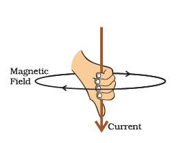
Imagine that you are holding a current-carrying straight conductor in your right hand such that the thumb points towards the direction of the current. Then your fingers will wrap around the conductor in the direction of the field lines of the magnetic field, as shown in Fig. This is known as the right-hand thumb rule.
Maxwell’s corkscrew rule.
If we consider ourselves driving a corkscrew in the direction of the current, then the direction of the rotation of the corkscrew is the direction of the magnetic field.
Magnetic Field due to a Current through a Circular Loop
The magnetic field produced by a current-carrying straight wire depends inversely on the distance from it. Similarly, at every point of a current-carrying circular loop, the concentric circles represent the magnetic field around it would become larger and larger as we move away from the wire.
Magnetic field lines of the field produced by a current-carrying circular loop

By the time we reach the centre of the circular loop, the arcs of these big circles would appear as straight lines. Every point on the wire carrying current would give rise to the magnetic field appearing as straight lines at the center of the loop. By applying the right-hand rule, it is easy to check that every section of the wire contributes to the magnetic field lines in the same direction within the loop.
If there is a circular coil having n turns, the field produced is `n` times as large as that produced by a single turn. This is because the current in each circular turn has the same direction and the field due to each turn then just adds up.
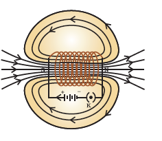
Activity
👉 Take rectangular cardboard having two holes. Insert a circular coil having a large number of turns through them, normal to the plane of the cardboard.
Magnetic field produced by a current-carrying circular coil.

👉 Connect the ends of the coil in series with a battery, a key and a rheostat.
👉 Sprinkle iron filings uniformly on the cardboard.
👉 Tap the cardboard gently a few times. Note the pattern of the iron filings that emerges on the cardboard.
Magnetic Filed due to a Solenoid.
A coil of many circular turns of insulated copper wire wrapped closely in the shape of a cylinder is called a solenoid.
Field lines of the magnetic field through and around a current-carrying solenoid.
Compare the pattern of the field with the magnetic field around a bar magnet. Do they look similar?
Yes, they are similar. In fact, one end of the solenoid behaves as a magnetic north pole, while the other behaves as the south pole. The field lines inside the solenoid are in the form of parallel straight lines. This indicates that the magnetic field is the same at all points inside the solenoid. That is, the field is uniform inside the solenoid.
Electromagnetic Induction
The production of electricity from magnetism is called electromagnetic induction. For example when a straight wire is moved up and down rapidly between the two poles of a horseshoe magnet, then an electric current is produced in the wire.
If a bar magnet is moved in and out of a coil of a wire, even then an electric current is produced in the coil. This is also an example of electromagnetic induction.
The phenomenon of electromagnetic induction was discovered by British scientist Michael Faraday and American scientist Joseph Henry independently in 1831. The process of electromagnetic induction has led to the construction of generators for producing electricity at the power stations.

A galvanometer is an instrument that can detect the presence of a current in a circuit. The pointer remains at zero (the centre of the scale) for zero current flowing through it. It can deflect either to the left or to the right of the zero mark depending on the direction of the current.
Very helpful notes ✌✌
ReplyDeleteThank you
DeleteVery nice
ReplyDeleteThank you
DeleteNice 👍👍
ReplyDeleteThank you
DeleteWell explained 👍👍👍
ReplyDeleteThank you
ReplyDelete